A cable for a mouse should be simple. Put 4 wires together, add a sheath, maybe a shield, and that’s it, right? Well yes, but it turns out there’s a lot of care that goes into every single aspect of designing a cable for a lightweight 8k mouse. Conductor choice and stranding, wire insulation material, insulation thickness, wire layout, shield type, jacket material … everything matters.
In designing the cable of the XA25, we had three goals:
- Electrically, it must adhere to required USB specifications.
- Mechanically, it should be minimally noticeable when using the mouse.
- Practically, it should not be excessively difficult to manufacture.
It turns out that these goals lie in tension with each other. There is a rather narrow window of specifications in which all three can be achieved. Before going into the exact choices made for the XA25, let’s first expand on each goal.
Mechanical goals
The goal is simple to state: the cable should feel like it’s not there. Of course, this is especially important for lighter mice; a cable that is unnoticeable on a 50 g mouse can become very bothersome on a 25 g mouse.
We can roughly classify into three categories the manners in which a cable is felt.
- Inertia. When you move a mouse around, a segment of the cable moves around with it. If significant, this affects the effective mass and balance of the mouse. To minimize this effect, the cable should of course be light. It should also be flexible, to minimize the length of cable that is dragged around.
- Pushing, pulling, and dragging. A rigid cable seeks to retain its shape. Any motion that bends the cable will be opposed, so flexibility helps here. In addition, the surface of cable is important. A braided cloth jacket can snag on the edge of the mousepad or on the edge of a desk. A rubbery jacket might result in significant drag as it glides on a mousepad. Ideally, the jacket is low-friction and smooth.
- Colliding with the cable. In games that require significant vertical motion, it is possible that a mouse runs over the cable when moving upwards quickly. This can become a significant issue for extremely flexible cables. Imagine a strand of noodle as the cable - it is easy to see how the mouse will run over the cable. Therefore, having a bit of stiffness is beneficial for avoiding this. Using a bungee reduces this issue by elevating the cable and reducing the length of cable on the mousepad.
Therefore, mechanically, the ideal cable is as light as possible, has a smooth exterior, and is very flexible, but not so much that it is easy to run over. This is straightforward: use thin, flexible materials as much as possible. Avoid foil shielding, which tends to be stiffer than spiral and braided shields. The only aspect that deserves some extra thought is the outer jacket of the cable.
Cloth vs plastic jackets
Let’s make one thing clear right away: the common configuration of having a cloth braid on the outside of a plastic jacket is pointless. For any such cable, it would be better to either remove the cloth braid or skip the plastic jacket. Adding material to a cable always increases mass and stiffness.
What is compared in this section are pure plastic jackets and pure cloth (braided) jackets.
Weight
Without specifics, neither has an intrinsic advantage. Roughly, minimally thick plastic jackets and minimally thick cloth braids should be comparable in weight.
Flexibility
Cloth has the advantage in flexibility, but only if the braid is not so tight that the wires inside are compressed against each other. This is important for plastic jackets too. As the plastic jacket is extruded around a cable’s core, it can shrink upon cooling and squeeze the core.
Ideally, the jacket of cable hugs the core snugly, but does not compress it. If the core is not held snugly, the wires and filler inside can move out of position. This sounds like a minor issue, but in fact it does affect the electrical performance of the cable. As discussed in the next section, it is important for a cable to have consistent geometry throughout its entire length.
Durability
A good plastic jacket has superior durability to a braided cloth jacket. Imagine running a cloth-jacketed cable over the edge of a wooden desk. Any fibers that snag and catch on a tiny edge will break and the jacket will eventually fray. A plastic jacket with reasonable abrasion resistance will be superior.
Or no jacket at all?
One type of aftermarket cable forgoes a jacket entirely: bare-braided cables. In these, there is no shield and the wires in the core of a cable are held together by braiding rather than by a jacket. The challenges here are that
- There’s typically too much separation between the USB data wires, such that the impedance will be out of spec (more in next section).
- Without shielding, it is challenging to pass emissions and immunity tests that regulatory authorities require.
- No one makes these in large enough quantities for commercial use. Manual labor is expensive. It could be possible to construct a braiding machine, but the previous issues still apply.
Electrical goals
An 8000 Hz mouse requires high-speed USB, which mandates signaling at 480 Mbps. At 2.083 ns per bit, transmitting data over a 2 meter cable is not to be taken for granted. Consider, for instance, that it takes approximately 10 ns for an electrical signal to propagate over 2 meters in a cable. At these speeds, transmission line effects are important and the USB cable should not be viewed as simply four conductors. Rather, the entire construction of the cable, including its dielectrics (insulation) work together to propagate an electromagnetic wave that carries data.
DC resistance
Before going into the more interesting stuff, let’s get the boring stuff out of the way.
The XA25 consumes about 80mA of current maximum. The voltage drop due to wire DC resistance should not be so high that the power delivered suffers. For this, even using 40 AWG wires is not a problem. 2 meters of 40 AWG copper has approximately 7 ohms resistance, giving a 0.56 V voltage drop. Even with 1.1 V voltage drop round trip, 3.9 V delivered to the typical 3.3 V LDO of a mouse is no issue.
As far as DC resistance is concerned, anything thicker than 40 AWG (lower than 40) is perfectly sufficient. In practice, if one seeks to use thin wires in an 8k mouse’s USB cable, signal integrity is always a far more stringent consideration than DC resistance.
Characteristic impedance
A key property of transmission lines is their characteristic impedance.
USB 2.0 specifications require 90 Ohms +/- 15% differential impedance and 30 Ohms +/- 30% common-mode impedance. As USB employs differential signaling, the most important quantity is the differential mode impedance. Cables that deviate from these values will lead to signal reflections, which can corrupt data.
What controls impedance
The impedance of a cable is not a quantity defined end-to-end like resistance. It is better to envision it as a parameter related to the cross-sectional geometry of the cable at every point along its length. It is primarily related to the cross-sectional geometry: the size of the conductors, their separation, and the dielectric constant of whatever is in between. To be a bit more precise, impedance
where is the signal propagation velocity and is the capacitance per unit length. Assuming non-magnetic materials, where is the speed of light and is the (effective) dielectric constant of everything in between the conductors. The capacitance per unit length has no simple formula, but it increases linearly with the dielectric constant. As a general rule, smaller conductors with greater separation lead to lower capacitance.
If one seeks to tune a cable to hit the correct impedance spec, it is helpful to keep in mind: strong dielectrics, bigger conductors, and thinner insulation between conductors all lead to lower impedance.
The implication for making a thin and flexible cable is that once a conductor size is chosen, one should pick the weakest dielectric constant wire insulation possible, and then gradually increase insulation thickness until reaching the low side of the 90 Ohms +/- 15% differential impedance spec.
Geometric consistency
Since impedance is defined at every point along the length of the cable, it is important for a cable to have consistent geometry throughout. If wires get out of place, or extra filler strands get in between the conductors over some centimeters, this can introduce impedance discontinuities that lead to degradation of the signal. This is why it is important for the outer jacket and/or shield to be fairly snug and constrain motion of the wires within the cable.
Signal integrity and attenuation
The other aspect of USB cables that is nontrivial is the fact that high frequency signals are attenuated. In time-domain, this means that the edges of the signals are smeared out. If attenuation is excessive, data will become corrupt and the consequences would be (in increasing order of severity) silent data re-transmission, dropping packets, dropping connection entirely, or complete failure to enumerate.
The precise requirements for this are written in the USB 2.0 specification as both frequency-dependent attenuation limits and as eye-pattern masks. Tests using these will be shown below for the case of the XA25 and its cable.
What controls attenuation
A more detailed introduction can be found here.
The first thing to always keep in mind is that attenuation scales with length. A cable poorly designed, in terms of attenuation, can still be acceptable in sufficiently short lengths.
In terms of the parameters of the cable, attenuation is
where , , , are the resistance, inductance, dielectric conductance, and capacitance per unit length, respectively, and is angular frequency. (Sorry, I am not an engineer, and I refuse to use for imaginary.) Keep in mind that skin-effect is very important at the frequencies (100s of MHz) relevant for high-speed USB signaling. In addition, dielectric conductance at these frequencies stems nearly entirely from dielectric loss, typically described as “loss tangent”
.
For typical parameters relevant to USB cables, we can approximate and . Then, the attenuation
.
In terms of the characteristic impedance and propagation velocity,
.
Now to optimize a cable, the impedance cannot be adjusted very much, as it is constrained by USB specs. The propagation velocity does not have much variability either. As long as a low-loss dielectric is used, such as most fluoropolymers, the second term is orders of magnitude less than the first. (An exception is ETFE, which has a peak around 100MHz.)
Therefore, assuming that one has picked a low-loss dielectric and is adhering to USB specs for impedance, the most important variable is the numerator of the first term: , the AC resistance. At 100s of MHz, skin-effect is significant, and essentially there is no way around this except by picking sufficiently thick conductors in the wiring.
In summary: signal attenuation is minimized by using low-loss dielectrics and using thick conductors. Of course, the second is antithetical to making a flexible cable. In practice, this is the strongest constraint on making a cable thin, since the impedance requirements require that insulation thickness scales linearly with conductor thickness.
In our experience testing various cables at 2 meters length, high-quality 36 AWG cables are extremely marginal, 34 AWG is marginal, and 32 AWG is comfortable.
Radiated emissions and immunity
We will say more about this after the XA25 undergoes testing at a lab for radiated emissions and immunity.
A few notes however:
- More shielding and higher coverage shielding helps.
- Data wires should be arranged symmetrically to ground wire, to minimize common mode conversion.
- Ferrite chokes can help.
- Termination is important, and pigtails (the unshielded part of the cable near terminations) should be minimized.
What if these specs are not met?
Usually nothing. Most host controllers are designed to tolerate USB devices and cables that fall a bit short of the required specifications discussed above. But the implications are different for individuals, for modders, and for companies making a USB device such as a mouse.
For an individual, using a non-compliant cable that empirically works on their PC is no issue. In general, usually the USB data is either transmitted perfectly, or so poorly that the mouse fails to work at all. There’s a rather narrow window in which occasional packets are silently re-transmitted or dropped.
For a modder selling an aftermarket cable, it is relatively acceptable if only 95% of customers have no issues. The remaining 5% always have the option to revert to their stock cable if the aftermarket one is problematic. The fact that they are willing to tinker with their mice means that they are likely understanding of any issues that arise.
But for a company selling a wired 8k mouse, a situation where a few percent of customers have cable issues is rather unacceptable, as each instance can lead to returns, warranty replacements, and negative reviews. The only solution is to design the cable to be safely within USB specs. This is why most wired 8k mice tend to have thick cables, and why 8k wireless mice tend to include unbearably stiff and heavy USB-C cables to connect to their dongles.
How the XA25’s cable is constructed
Length
1.7 meters outside the mouse. 1.8 meters including the length inside the mouse.
Conductors
32 AWG stranded copper. This is the smallest diameter (highest AWG) that our cable manufacturer is willing to use, since thin wires are difficult to process and solder onto USB plugs.
Wire insulation
FEP (fluorinated ethylene propylene). FEP has the advantages of
- low dielectric constant
- low dielectric loss
- low friction (even if each individual wire is flexible, they become significantly stiffer together if they cannot slide against each other)
- being relatively flexible
The thickness of the FEP insulation was tuned for a differential impedance of 84 ohms, comfortably within USB specs.
There’s a couple other good options including PFA, PTFE, and ETFE. ETFE is stiffer and suffers considerable dielectric loss at frequencies relevant to high-speed USB. PTFE and PFA are considerably more expensive and have few upsides relevant to a USB cable. Perhaps the only downside of FEP is its lower fold endurance than PFA and PTFE, but this is not an issue unless the cable is severely kinked. The outer jacket and shield provide a lower limit to the bend radius, so the wires inside will never see excessive strain.
Fillers
Two bundles of Kevlar filler run in parallel to the wires. These serve two purposes:
- Maintain an overall round geometry of the entire cable
- Increase the tensile strength of the cable
Shielding
High-coverage braided shield, made of tinned copper strands. As mentioned previously, foil shields are stiff. Spiral shields are another option, but these are awful for signal integrity, due to some inductive coupling between the shield and the wires. Braided shields have neither issue.
Cross section
Here’s a cross-section of the XA25’s cable that shows how all of the above are arranged:
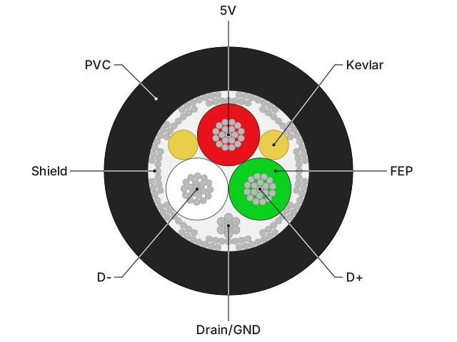
Where’s ground?!
Of note here is that there is no separately insulated ground wire! The drain wire and shield are used together as the ground. This is an unconventional decision but it allows for
- Bundling of the other three wires into a stable triangular geometry
- Approximately 0.1mm less overall thickness of the cable
- Simplified termination on the mouse PCB (4 pins instead of 5)
Does this have any downsides compared to the conventional arrangement with an insulated ground wire? Empirically, I’ve yet to measure any downsides to this arrangement.
Theoretically, well here’s what the best AI models have to say:
Fable 5 Max: https://claude.ai/share/bc35c489-f3da-4a5c-8bf5-96470d305a36
GPT 5.6 Sol Max: https://chatgpt.com/share/6a8d4c40-d120-83e8-b220-bb9ab6fbeebf
Outer jacket
Primarily for the reasons of durability, we chose to not use a braided cloth jacket. A secondary benefit of a plastic jacket is that the core geometry can be constrained without being compressed.
A smooth and flexible PVC jacket was chosen. The composition used in our cable’s jacket is phthalate-free and REACH-compliant. There are a number of other possible flexible options: silicone, TPE, TPU. These options tend to be higher friction, although low-friction formulations exist. TPU shrinks more during the extrusion process, leading to a compressed core that’s more stiff than what can be achieved by PVC.
How the XA25’s cable measures
Basic properties
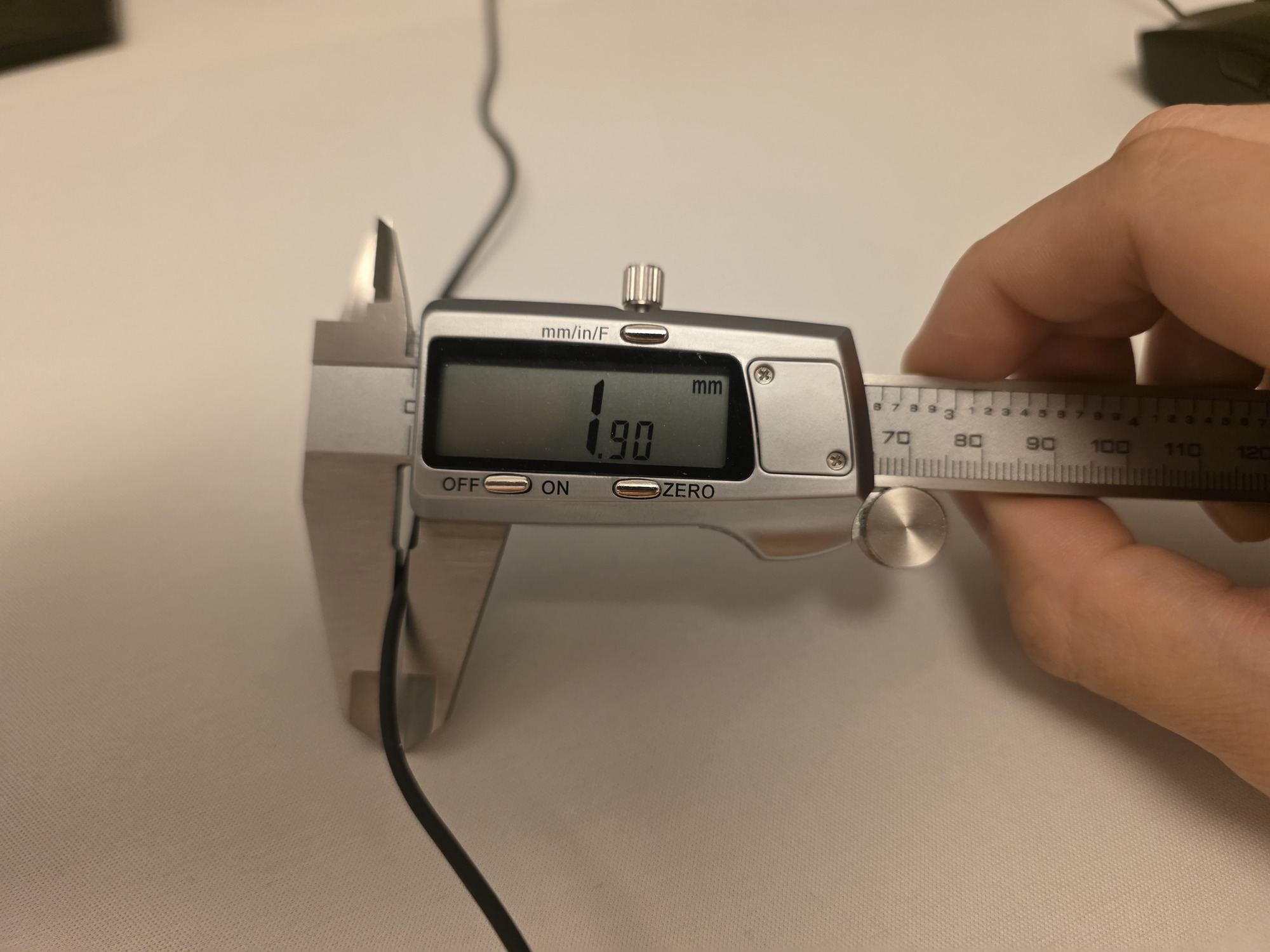
Mass per unit length: 6.9 g/meter.
Diameter: 1.9 mm.
Flexibility
I don’t know a good way to measure this objectively. All I can say is that the XA25’s cable is more flexible than any other 8k mouse’s stock cable. The Zaunkoenig M3K cable is the closest comparison, and it’s noticeably stiffer. No wireless mouse’s USB-C cable comes close. The only cables more flexible than the XA25’s cable are aftermarket cables that forgo shielding and/or use a headphone-wire style wiring.
Differential impedance: VNA measurements
The best way to measure characteristic impedance is to use a vector network analyzer (VNA). While we have an inexpensive NanoVNA, we don’t have a proper fixture to measuring this in differential mode. Our cable manufacturer does, and shared this measurement with us:
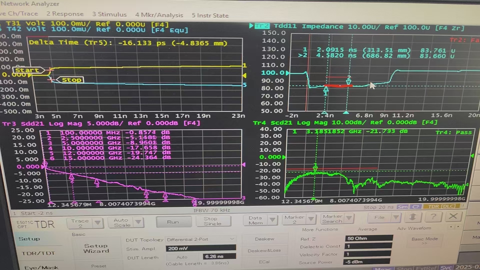
84 Ohms (see top right region) is comfortably within the range [76.5, 103.5] specified by USB.
Differential impedance: TDR measurements
Another way to measure characteristic impedance is to perform time-domain reflectometry. This can be done relatively easily using an oscilloscope and something to generate edges. I used Raspberry Pi Pico with a JST connector soldered and glued onto it. The Pico is programmed to output a square wave. When the cable is connected but unterminated on the USB end, a series of reflections is visible.
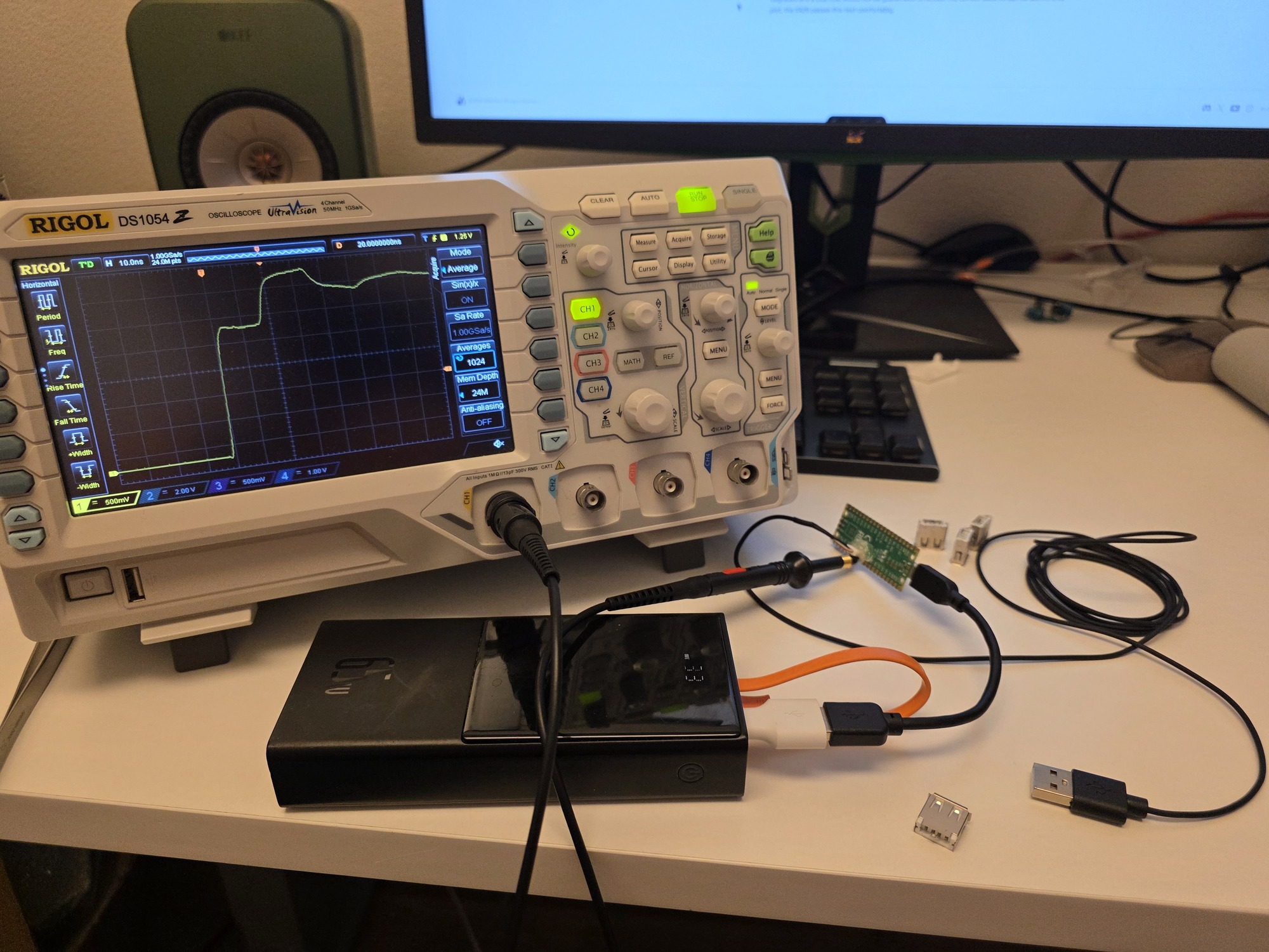
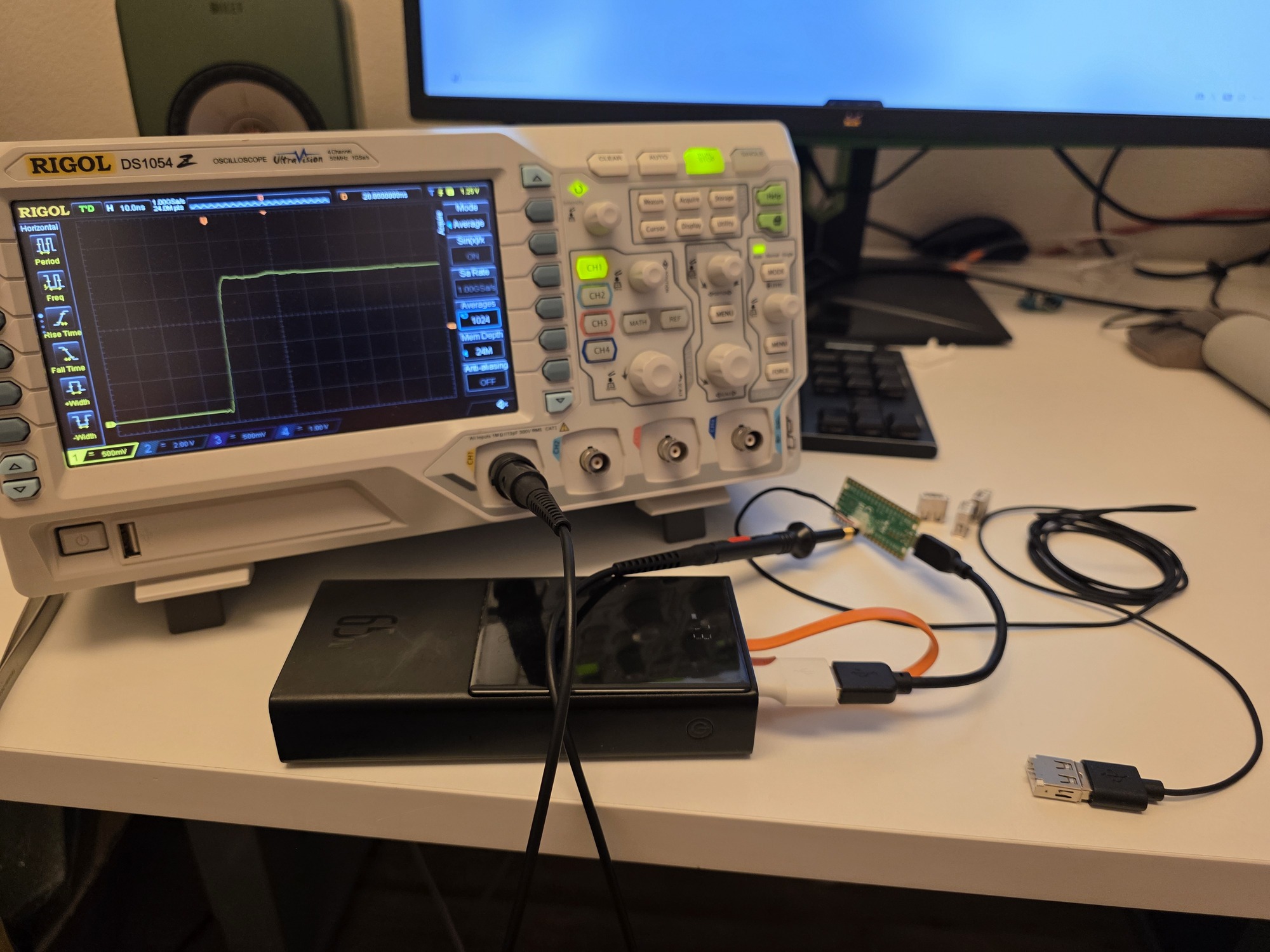
Adding a USB port with a 82 ohm resistor eliminates reflections essentially perfectly, as expected given the previous VNA measurements.
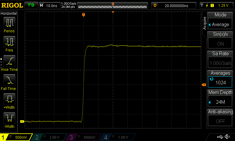
Note that, on first glance, the mode excited here does not seem to be a differential mode. D- is connected to the Pico’s GPIO pin that has a square wave output, and D+ is connected to ground. But since the other wires are left floating (and not in any physical proximity to the scope ground) and the Pico is battery powered, there is no return path for the current sent in D- except through D+. Therefore the mode that is excited is precisely the differential mode.
Signal integrity: eye pattern test
Performing eye pattern tests to verify signal integrity requires some serious equipment. We have an HP/Agilent 54846A oscilloscope, with 2.25 GHz bandwidth. This was state-of-the-art equipment, from 25+ years ago. And yeah, it runs Windows 98. Used units still sell for several thousand dollars on eBay.
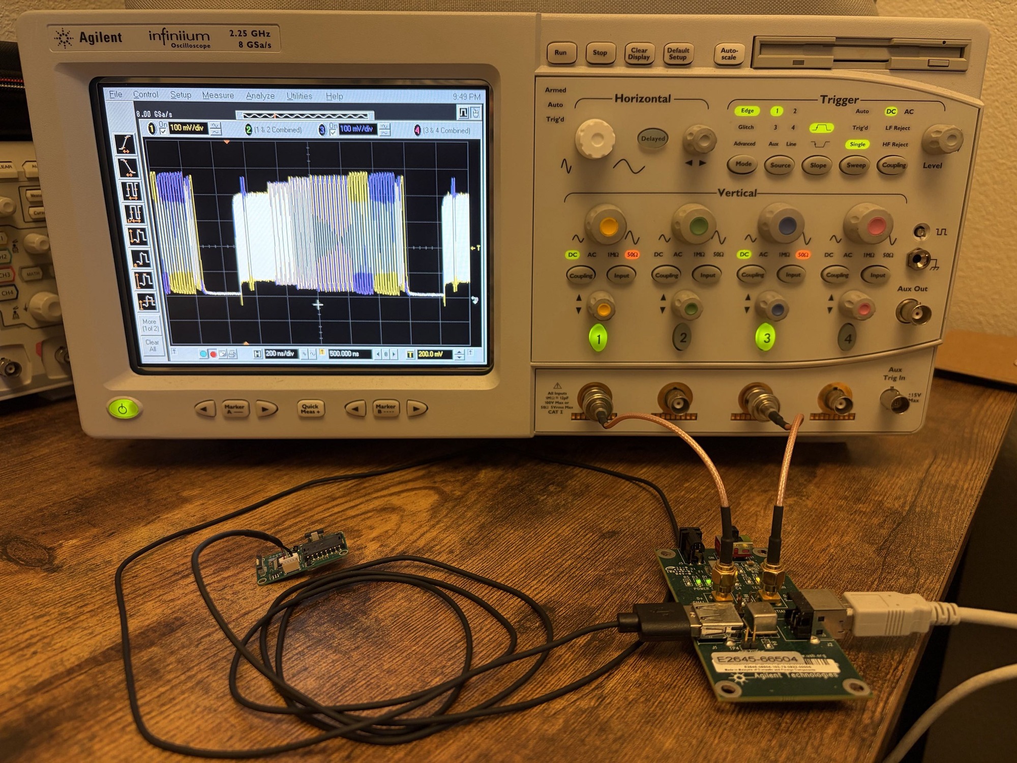
To conduct this test, the microcontroller of the XA25 is set into a USB test mode where it continuously sends test packets down the USB cable. A fixture directs the data straight into the inputs of the oscilloscope. This is the result after collecting and processing data.
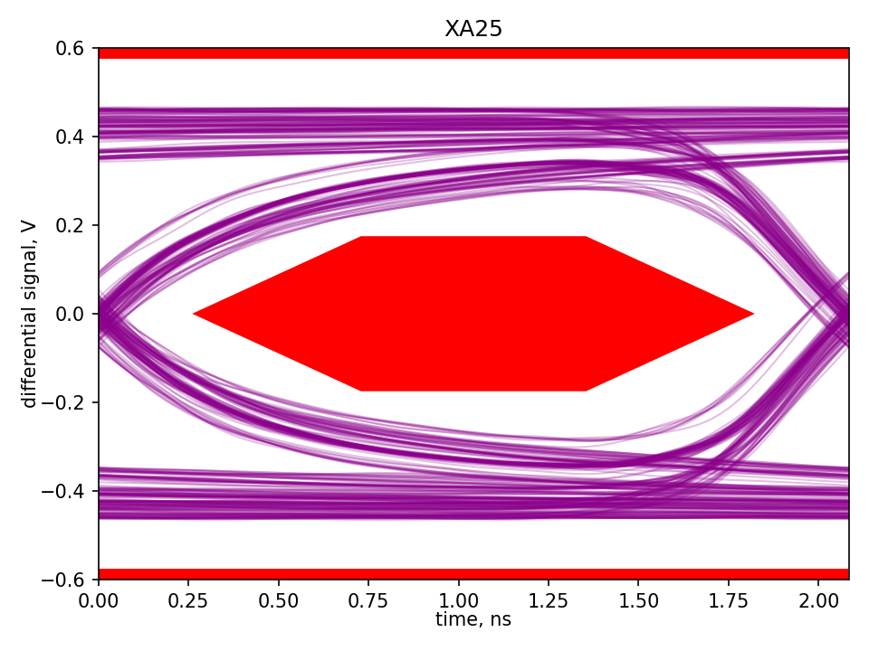
The purple curves indicate the differential voltage seen by the oscilloscope after the signal from the microcontroller has travelled across the 1.8 meters of cable and test fixture. If it intersects the red region in the center, that indicates failure of this test: the edges of the signal are too severely degraded and a USB host would not be guaranteed to recover the correct data. As can be seen in this plot, the XA25 passes this test comfortably.