Sensor implementation. Smoothing. MCU smoothing. Debounce latency. SPI synchronization. What’s the deal with all these mysterious terms? This post is an attempt to verbally explain all this while discussing some of the design decisions of the firmware of the XA25.
For the uninitiated, firmware is simply the code that runs on the microcontroller (MCU) of the mouse. The MCU is the “brain” of the mouse. In particular, it is responsible for communicating to the PC the state of the buttons, motion data from the sensor, and scroll motion from the wheel.
I will focus on wired mice. A wireless mouse has the additional stage where the MCU of the mouse needs to communicate over radio with the MCU of the receiver. Most of the considerations below are still highly relevant to wireless mice.
Minimal starting point
At a high level, mouse firmware is really simple. The MCU just needs to initialize everything; connect to the PC over USB; read the buttons, sensor, and wheel encoder; and send that over USB. The last two repeat in a loop. In C-like pseudocode,
int main(void)
{
    init_mcu(); // set up clocks and other miscellaneous stuff
    init_buttons();
    init_wheel();
    init_sensor();
    init_usb(); // tell the PC that this is a mouse

    while (1) {
        data_button = read_button();
        data_wheel = read_wheel();
        data_sensor = read_sensor(); // over SPI

        // push data into the USB peripheral data bank
        write_usb(data_button, data_wheel, data_sensor);
    }
}
If you were to write firmware for a mouse from scratch, this would be a reasonable high-level starting point, and you’d just need to implement each of those functions. For an actual product, some other high-level aspects would be handled as well, such as
- communication with configuration software
- firmware updates
- report rate limiting
Now once this is all done, why should tracking performance differ between any two mice with the same sensor? What controls and affects motion and click latency?
“Sensor implementation”
This awful phrase has led people to believe that sensor performance is mysterious, with some companies possessing some magic sauce that allows them to pull more performance out of a particular sensor than others using the same sensor. As with many other things, there is some truth to this, but ultimately it’s a gross simplification. Let’s clear this up.
As a quick summary of what affects sensor performance, there are essentially three things:
- How the sensor is initialized and its settings
- The timing of when data is read
- Not doing anything silly
Sensor settings
An optical mouse sensor is basically a camera that rapidly takes pictures of the mousepad, plus a tracking engine/processor that computes motion based on what the camera sees. When the MCU initializes the sensor, it sends a bunch of settings to the sensor to configure the parameters for taking pictures and computing motion. This is done by writing various numbers to registers on the sensor (i.e., addressed bytes of memory intended for data input and output). In the firmware, it kinda looks like
void init_sensor(void)
{
    // register address, value
    spi_write(0x12, 0x34);
    spi_write(0x45, 0x67);
    // etc
}
Naturally, these settings can impact the final tracking performance of the mouse, as in its accuracy and responsiveness. But unfortunately, maybe with the exception of the two largest gaming mice companies in the world, the meanings of maybe 90% of the registers are not disclosed. For the rest of us, we’re stuck simply using the long tables of registers and values that are given in the datasheet from PixArt.
Sometimes, one can reverse engineer the functionality of some of these undisclosed registers, as I did in the previous downshift blog article. But besides that, the overwhelming majority of companies are very much in the dark as to how exactly the sensor is configured.
A few registers/settings are worth mentioning briefly:
- DPI: this is the most obvious one. The sensitivity of the sensor (dots/counts per inch) is set by register settings.
- “Ripple control”: Better known as smoothing. Essentially this is a moving average filter on the sensor motion counts from each frame. Effectively it adds latency equal to half of the moving average window. Only relatively recently (afaik, since PAW3399) was this register officially disclosed. In previous sensors, it was either controlled by an undisclosed register or automatically toggled/increased beyond some threshold DPI.
- Motion Sync: This is so widely misunderstood and wrongly described, even by otherwise trustworthy individuals, that I’ll need to write a separate post concerning this at some point. Let me just state as succinctly as possible:
- The Motion Sync register does not affect the timing of SPI, since the MCU initiates and decides the timing of SPI communication.
- Using the Motion Sync functionality requires that SPI be read periodically. One way to do this is to synchronize the SPI to USB frames, but this is not strictly required.
- What Motion Sync does is some processing to hide the aliasing, seen in MouseTester plots of motion counts vs. time, of the non-integer ratio of sensor framerate to USB polling rate.
- Rest mode settings: For power efficiency, sensors have settings to decrease their framerate when they are idle for some time. This is especially relevant for wireless mice where battery life is crucial. If you’ve ever experienced a skip in the response of a wireless mouse that’s been idle for some time, this is why. For a wired mouse, there’s no harm in disabling rest mode entirely.
- DPI downshift settings, sensor framerate: These are undisclosed registers that were described in the previous blog post.
On the XA25, most of these settings are exposed in the control panel (hold Shift and click connect for a demo). Here’s a screenshot.
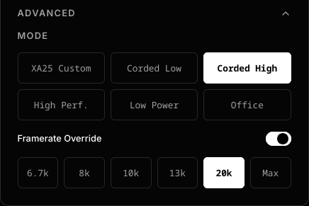
Under “Advanced”, the “Mode” selects the initialization sequence, including all five modes listed in the PAW3950 datasheet, and also a custom mode that is a tweaked version of the settings from the Razer DeathAdder v3 wired. The purpose of exposing the ostensibly lower performance modes such as “Low Power” and “Office” is in case these modes perform better on particular mousepads. A framerate override option is also exposed, allowing users to compare and try different modes under identical framerate settings. The only settings not exposed on the control panel are ones that, in my opinion, never belong on a mouse: ripple control and DPI downshift, although I might enable toggles for these if there is sufficient demand.
Data timing and synchronization
In an ideal world, the sensor captures an image, processes it to compute a motion delta, which is immediately read by the MCU over SPI. Immediately after, a USB poll arrives, asking for data, and the MCU sends that data. This ideal scenario requires that the sensor framerate, SPI reads, and USB poll are all synchronized and phase locked. This is what the Razer Viper V4 Pro purportedly achieves in what they call “Frame Sync”, which requires newly developed features in their sensor.

This diagram is a helpful sketch to visualize the flow of data. In this ideal scenario, with the timing of each stage pushed right up against the next, the motion data are always being transferred and never stagnant, so latency is minimized. It remains to be seen how close the Viper V4 Pro comes to this idealized limit, as in how much latency remains in its data pipeline.
For all previous generation sensors, the timing of sensor frame capture cannot be controlled. Without this frame timing control, there is inevitably a mismatch between the sensor framerate (e.g. 20000 Hz) and the USB polling rate (e.g. 8000 Hz).

As shown in this diagram, for these example numbers (20000 Hz and 8000 Hz), the data read by the MCU and sent over USB will alternate between showing 2 and 3 frames of data, as the gray funnels show. Plotting raw motion counts against time (e.g. by MouseTester xCounts, when Motion Sync is off) will show corresponding aliasing patterns.
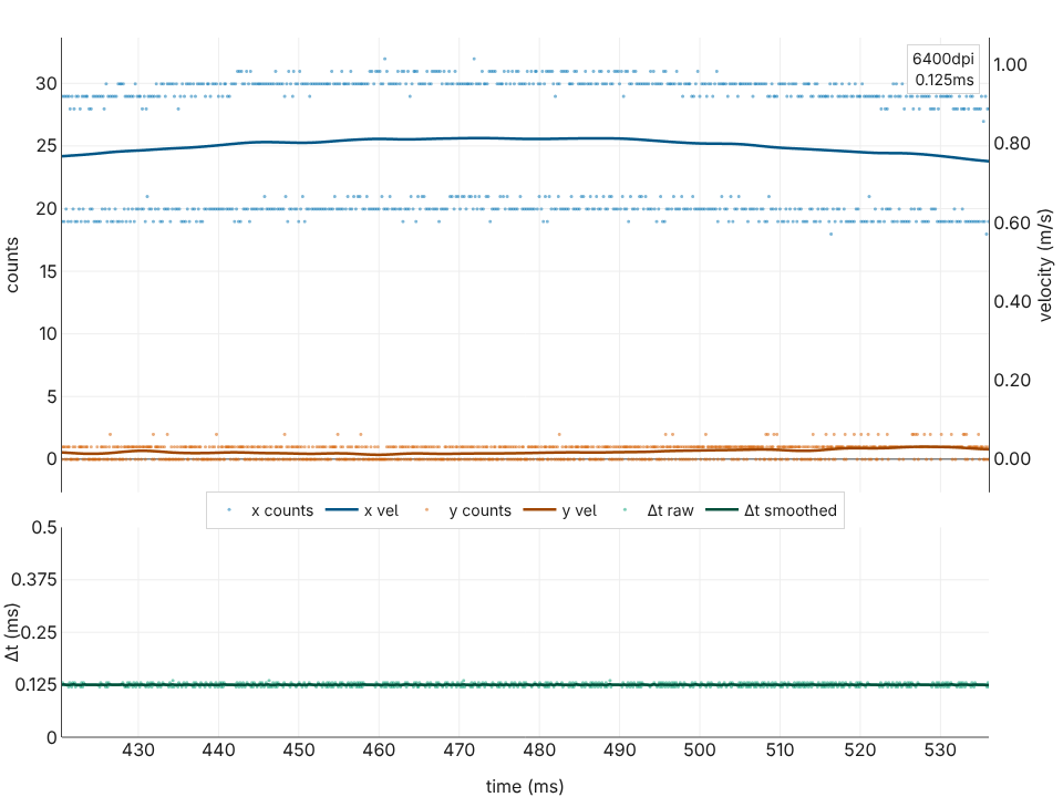
Here’s an example of aliasing. (This is plotted by MousePlotter, a browser-based version of MouseTester that I haven’t officially released yet. Try it out on Chromium-based browsers here). Each frame gives roughly 10 counts of motion, and this plot shows alternating 20/30 counts corresponding to 2 and 3 frames’ worth of data. More examples of aliasing can be found in various old overclock.net posts of mine such as this. Strictly speaking, this effect adds a bit of stutter in the cursor/screen tracking, but in most cases, the mismatch between USB rate and monitor refresh rate is a much more significant factor.
While these limitations are insurmountable, firmware should still control the timing of SPI reads to minimize latency and avoid introducing additional aliasing. There are two approaches that are equivalent and optimal: synchronizing SPI reads to USB polls, or synchronizing SPI reads to new motion data. The important thing is to avoid introducing additional timing mismatches. In the section on Latency below, we’ll discuss more on this and on the choices and optimizations implemented in the firmware of the XA25.
Avoiding silliness
Once the above points are taken care of, one will have a reasonably performant sensor, if the pitfalls below are avoided:
- MCU Smoothing: this is rare now, but in the past, some mice applied a moving average filter in the firmware. I first discovered this here.
- Report descriptor integer width: When one uses high DPI, using integers with not enough bits in the USB report leads to either clipping of the motion data or wraparound. This was a common issue 20 years ago when 8-bit integers, for which values cannot exceed +127 or -128, were common. Nowadays, it’s fairly universal to use 16-bit integers everywhere for motion deltas, whether it’s sensor output or USB reports. 16-bit allows motion data up to +32767, and at 1000 Hz report rate, one would need to move a 30000dpi mouse at 27.7 m/s to saturate this limit. Still, occasionally, some mice mess this up in strange ways like using 12-bit integers.
- USB double buffering: This is more subtle but can add unnecessary latency. On MCUs with dual data banks, you might add an additional USB frame’s worth of latency if you write to a data bank while data in the other one has not transferred yet.
- Everything else in firmware: Mouse firmware also handles communication with the configuration software, setting RGB lighting modes (which thankfully are declining in popularity), debouncing switches, etc. It is important to ensure that performance, especially the timing of sampling the sensor and clicks, is not impacted by these miscellaneous tasks that the firmware must periodically execute. In general, maintaining a clear mental picture of how the data flows from sensor to MCU to USB cable is helpful to assess whether firmware features impact performance.
Besides firmware, having the PCB designed properly, the USB cable not dropping packets, etc., are also necessary for optimal tracking performance. Any such hardware issues tend to make the mouse stop working entirely, so their effects are rarely subtle.
Latency
Suppose two mice use identical register settings and neither does anything silly in its firmware. The only difference in sensor performance between these two mice is in their latency, including the consistency of latency. This is purely a matter of the timing of when data flows.
Theoretical limits
Ideal scenario with frame timing control
Let’s first analyze the latency of the ideal scenario, as described earlier, where the timing of each frame can be synchronized with SPI and USB. Suppose some physical event occurs at a particular time. The event might be something like initiation of motion, passing some specific position on the mousepad, changing direction of motion, etc. The motion latency of a mouse is defined as how much time elapses from the time of this event to the time of completion of the USB report containing data reflecting this event.

In this diagram, the dark dot represents the physical event. The latency here is the sum of and .
is the sum of the sensor processing time, SPI read time, and USB poll + report transmission time. The latter two are highly deterministic, with < 1 µs variation, and can be modelled as constants. The sensor processing time is unknown, but it is a reasonable assumption to treat it as constant as well. Given that current sensors run up to slightly over 20k frames per second, the sensor processing timing is probably around 40 µs. SPI read time is about 5 µs. (The SPI clock rate is 16 MHz, which gives 0.5 µs per byte. The motion burst address byte is 0.5 µs, the datasheet requires a 1 µs gap until burst read, and reading 6 bytes takes 3 µs, so 4.5 µs is the absolute minimum of SPI activity.) For a USB poll and report (IN and DATA), with high-speed USB, the time used is < 1 µs and negligible. In total, .
is the time between the physical event and the last instant that the sensor captures data. Assuming no relation between the timing of these, can be modelled as a uniform random variable between 0 and 125 µs, which we write as , where denotes “is distributed as”.
The total latency
This has expected value .
This number represents the absolute floor for hardware of this speed (40 µs frame processing time, 16 MHz SPI clock, 8000 Hz USB polling). Increasing the framerate, say to 16000 Hz, cannot decrease the latency. At best, with sensor timing pushed right up against the SPI reads, one matches the ideal 8000 Hz scenario analyzed here.
If one works with a sensor that is capable of synchronizing its frame timing to SPI, this value represents the minimum possible latency. The goal when developing firmware is to minimize any gaps between completion of sensor processing and SPI reads, and between completion of SPI read and USB transmission. Any such gaps increase and overall latency.
Ideal scenario without frame timing control
If the timing of sensor frames cannot be synchronized, as is currently the case for all sensors besides the sensor in the Viper V4 Pro, one still needs to decide when to perform SPI reads. As mentioned previously, the key thing is to avoid additional aliasing patterns/artifacts by either
-
SPI reads synchronized with USB polling. This was what was drawn previously, which I reproduce here
In this scheme, ideally the SPI read finishes right before the USB poll arrives, since this time gap directly adds latency. (Again, as mentioned previously, this is NOT Motion Sync. For instance, the original G502 and G303 synchronized SPI reads to USB frames, several years before Razer introduced the term “Motion Sync”.)
-
SPI reads synchronized with the arrival of new motion data from the sensor, but overwriting the USB peripheral data bank if it has data already so that all the motion counts are coalesced.

Ideally, the update of the data bank should be atomic. Otherwise, the gap between when the data bank is cleared and re-written becomes a window in which a USB poll might not receive a response, leading to missed reports. Unfortunately, the type of atomic updates of USB banks is not possible for the vast majority of USB microcontrollers.
For conciseness, let’s only analyze the latency of approach 1. It’s straightforward to show that an identical analysis applies to approach 2.

As before, the dark dot represents the physical event, and the latency is . When the event occurs, the frame in processing has already captured its image, so the event is only registered at the next frame. is the time from the event to the completion of that next capture, and is the time from there until the completion of the USB report carrying the data. Unlike the synchronized case, is no longer constant. The captured frame finishes at an arbitrary phase relative to the beginning of the SPI read, so its data must wait a variable amount of time for the next SPI read before it is sent.
If we assume that the sensor framerate is not a commensurate multiple of the USB polling rate (i.e., their ratio is irrational), the equidistribution theorem allows us to model and as uniformly distributed random variables. This is a reasonable assumption because even if the sensor framerate is nominally set to 8000 Hz, the sensor’s internal oscillator has precision and stability only around 1%, so the timing of frames will almost never be locked to USB polling rate.
In equations, where is the sensor frame period. , where is the period of SPI reads and the 45 µs is assumed to be similar to the value in the previous section. The total latency
has expected value .
This is the floor if frame timing control is not available.
What the XA25 does
The MCU (Nuvoton M483) of the XA25 cannot do the type of atomic update needed for approach 2, so approach 1 is used. Actually, I’m not aware of any mouse that uses approach 2. (Although, to the best of my understanding, the classic MLT04 SoC merges the functionality of MCU and sensor and acts equivalently to approach 2.)
To achieve the limit of what’s shown in approach 1, what the firmware has to do is delay the SPI read all the way until just before the USB poll arrives. The main loop of the firmware should be something like:
    while (1) {
        /* ... everything else ... */

        delay_microseconds(X)

        data_button = read_button();
        data_wheel = read_wheel();
        data_sensor = read_sensor(); // over SPI
        write_usb(data_button, data_wheel, data_sensor); // load USB data bank

        block_until_usb_poll(); // increase X to make this as short as possible
    }
One approach to minimizing the time spent waiting for the USB poll is to insert a delay before all the reads. For example, this was done in the M3K’s firmware as a hard-coded delay. However, if one seeks to shave off the last microsecond of latency, this approach has two issues:
- because oscillators are not perfectly precise, 125 µs on some host controllers might be slightly shorter than 125 µs, and X µs on some mice might be slightly longer than X µs. Unless some margin is provided (so not delaying as long as possible), there’s a risk that by the time
write_usbis called, the poll has already come and the window to respond has elapsed. This margin directly contributes to latency so it should be kept as small as possible. - if
read_wheel()takes more time than usual, such as when scrolling, orread_button()takes more time than normal, there’s also the risk of a missed poll for the same reason.
The XA25 addresses the first issue by using a dynamically adjusted delay to ensure that polls are not missed, while keeping the margin minimal. For the second issue, the code for reading buttons, wheel, and sensor is implemented to run in constant time, irrespective of scrolling, clicking all 5 buttons at once, etc. The result from these optimizations is that the XA25 comes to within a few microseconds of the theoretical limit discussed above.
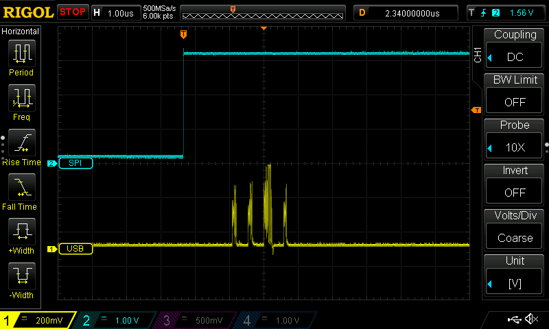
In this oscilloscope screenshot, the blue trace is the SPI SS pin. Its rising edge indicates completion of the SPI read. The yellow trace is the USB D- line. On the USB line, 4 packets are visible. These are the start-of-frame (SOF) packet, IN token (the poll), DATA packet (the mouse report carrying data), and ACK (acknowledgement from host that the data has been received). Compared to the ideal scenario described previously, where the USB poll and report immediately follow the SPI read, the XA25 has roughly a 2.3 µs gap. This is what is meant by the “latency overhead” on our home page.
The other aspect that’s optimized is this: no matter how the sensor is moving, how many buttons are being clicked and how the wheel is scrolled, the timing of reading the inputs is synchronized to USB frames with < 0.2 µs jitter. This is hard to show via a picture, so you’ll have to wait for a video to actually see this.
We also plan to perform real measurements of motion latency. However, since we’re interested here in approaching the theoretical limits to within a couple of microseconds, these would only be meaningful if a measurement rig had microsecond-level precision. This is not easy. Here are the two best setups I’ve seen so far: https://b23.tv/sRcyZHw and https://x.com/Tw1tterIsGood/status/1911351123723862480/video/1.
Click latency
Most of this will be saved for a part 2 post. There’s a lot to say about debouncing, optical switches, virtual switches like Logitech’s HITS system, etc, and this post is already getting quite long.
As far as the theoretical limit of latency is concerned, all the previous information applies if one thinks of a switch as an infinite framerate sensor, with 0 processing time and 0 SPI read time. The theoretical limit is that the click latency is , which has expected value 62.5 µs.
We’ve recently gotten a USB analyzer and done some measurements that confirm that the XA25 has click latency of roughly 65 µs.
USB caveats
All the previous discussion has relied on an assumption that is mostly true in practice, but not guaranteed: that USB polling is perfectly periodic with 125 µs intervals.
First, it is important to distinguish between “polls” and “frames”. USB transactions are organized around frames. In 480 Mbps high-speed USB, these are periodic 125 µs intervals (officially called “microframes”, but we’ll keep using the term “frames” for simplicity). At the start of each interval, the host sends a start-of-frame (SOF) packet. After that, the host can poll for data, the device can send data back, etc. Finally, there’s a brief end-of-frame period at the end of each interval that’s guaranteed to be quiet. You can read all about this in the USB 2.0 specification. It’s a long document, so if you’re interested, I recommend asking AI to refer you to the right parts of it.
The key points relevant to us are the following:
- The USB 2.0 specification mandates that the timing of SOF packets be very periodic. The allowed variation is +/- 500 ppm, which corresponds to +/- 62.5 ns.
- SOF packets are not the polls. The polls are, in USB terminology, IN token packets.
- The USB specification does not specify any constraints for the timing of polls (IN tokens), except that they do not take place during the end-of-frame period. It does require that the device respond essentially immediately to the poll with either a DATA packet or a NAK packet (meaning no data to be sent).
In principle, with an oddly designed host controller, the polls could arrive in a very non-periodic fashion. In practice, what I have observed by looking at oscilloscope traces of devices connected to my various PCs is that:
- SOF packets are basically perfectly periodic, with < 10 ns jitter.
- IN tokens come immediately after the SOF packet. In some situations discussed below, I’ve observed single-digit µs levels of jitter.
By the way, a quick word on MouseTester plots
This kind of single-digit µs jitter is NOT what is typically seen in MouseTester interval/frequency graphs. For example, the plots here show jitter of hundreds of µs. This is because MouseTester and similar programs plot the timing of when it, the program, receives the mouse motion data. Between when the mouse report is on the USB cable and when MouseTester receives that data, there are several stages of data being routed by the OS kernel, CPU wake-up latencies, etc, that add jitter to this timing. To really know how stable polling is, one needs to use an oscilloscope connected to the USB data lines or a USB analyzer (or alternatively, write custom firmware that detects when polls occur). The main takeaway here is that such huge levels of jitter seen in MouseTester plots are not related to the mouse firmware at all, and should never be used to judge the performance of firmware.
What happens when you have multiple devices on the same host controller? Or even with one device, multiple endpoints (e.g. one endpoint for a mouse, one for a keyboard, one for configuration software communication)? USB 2.0 has a shared bus topology such that the host controller polls each endpoint of each device consecutively, in some order determined by the controller. The consequence is that if A is polled first, the timing of when B is polled might depend on whether A responds with DATA or with NAK. These are generally microsecond-level effects, but they are real.
It is for these reasons that the XA25 firmware is designed to have only a single endpoint, for the mouse reports, that is polled regularly. The data on the USB bus is kept as minimal as possible to eliminate any possible effects related to multiple endpoints. (Of course, if you plug in other devices on the same host controller, that can affect things, but that’s outside my control.) The cost of having only a single polled endpoint is that the XA25 lacks the ability to rebind its buttons to keyboard keys, which unfortunately affects a small fraction of users who rely on this. For software configuration, another endpoint is used to enable communication, but the report descriptor is written in such a way that usually, this endpoint is never polled. The exception is on Linux, and only when the control panel is open and connected to the mouse. In this specific situation, there’s a poll every 4 seconds.
Operating system effects
As you might have noticed in the last part of the previous paragraph, the operating system can choose to poll an endpoint or not. This is in fact relevant for the mouse endpoint. For example, on Linux, if you’re in a TTY, the mouse endpoint is not polled at all unless you run some program that uses the mouse.
Even then, it should not be taken for granted that it is polled every single frame. The key point is that the kernel or operating system can control whether or not a poll happens, though the timing of when the poll occurs within a frame is up to the host controller. And actually for 8000 Hz mice, it is actually a fairly common occurrence for the kernel to skip a poll, especially in the frame immediately following the first report after an idle period. Basically, the CPU needs to process that report, then tell the host controller “hey, poll again on the next frame”. If that communication to the host controller doesn’t occur quickly enough, the host controller won’t get the request to poll again. Once reports are coming in regularly every single frame, the CPU tends to be awake enough to respond quickly, assuming that the system is not overloaded.
It is easy to mess up how these missed polls are handled in firmware. If the USB data bank is already full, there are three possibilities for what write_usb(...) should do:
- save the data that you were gonna write to the USB data bank, and try again next time. However, this means that the transmitted data once the next poll comes is stale.
- overwrite the data in the USB data bank with the current frame’s data. This means that the previous data was lost, so if that involved motion, you’ve thrown away some motion counts.
- overwrite the data in the USB data bank with the current frame’s data combined with the previous untransmitted data. This ensures that when the next poll arrives, it transmits the freshest data without losing any motion counts. This is the best approach and it is what the XA25 firmware does.
What’s next
Stay tuned for subsequent posts that will discuss Motion Sync, button debouncing, wheel debouncing/robustness, and some other nice features of the XA25 firmware.